Cooling System Pumps
What is a Cooling System Pump?
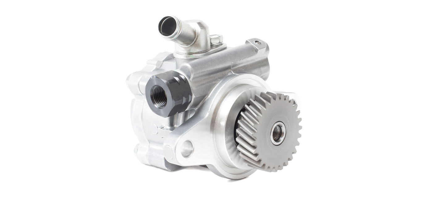
A cooling system pump plays a crucial role in maintaining optimal operating temperatures by circulating water throughout the system. This continuous flow helps prevent overheating in various types of equipment. Typically, the pump operates within a power range of 30 to 100 watts. Its core components include an impeller, a motor, and an inverter, all enclosed within a cylindrical housing. In this article, we’ll delve into how the pump works, its structural design, and the electronic elements that drive its performance.
Cooling System Pumps in vehicles
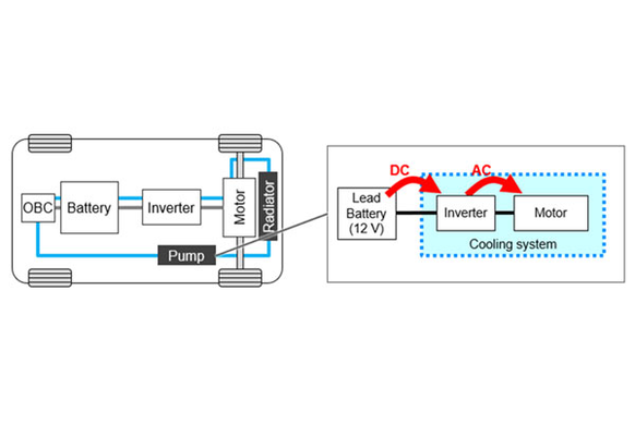
In automotive applications, cooling systems are engineered to regulate the heat produced by key components such as the battery and motor. This is achieved by channeling water through a network of pipes embedded in the cooling jacket that surrounds these parts. The pump ensures consistent water circulation, powered by 30 to 100 watts depending on the system’s demands. Its internal structure comprises an impeller for water movement, a motor for mechanical drive, an inverter to control motor speed, and a circuit board - all housed in a compact cylindrical casing.
Market Trends and Growing Demand for Cooling System Pumps
With the global rise in vehicle production—spanning both electric vehicles (EVs) and traditional internal combustion engine (ICE) models—the demand for cooling system pumps is steadily increasing. As components such as batteries and inverters become more powerful, they generate greater amounts of heat, intensifying the need for advanced cooling solutions. This trend is driving the development of more efficient and robust pumps capable of handling higher thermal loads.
To support these evolving requirements, the electronic components within cooling systems must exhibit critical performance characteristics, including:
- High current capacity
- Minimal energy loss
- Exceptional heat resistance
- Accurate temperature regulation
Circuit Architecture of a Cooling System Pump
A typical cooling system pump integrates several key electronic modules to ensure reliable operation and thermal management:
- Noise Filter: Suppresses electrical interference using a coil and capacitor combination
- Voltage Conversion Circuit: Adjusts voltage levels via switching elements such as field-effect transistors (FETs)
- Current Measurement Unit: Tracks the motor’s output voltage for performance monitoring
- Gate Drive Circuit: Regulates the switching elements that control voltage conversion
- Control Circuit: Oversees the operation of the conversion system and coordinates other pump functions
- DC/DC Converter: Supplies power to the control circuit
- Communication Interface: Facilitates data exchange with external systems or devices

Detailed look at individual circuits and components
Noise Filter - this circuit element mitigates electrical noise originating both internally and externally, helping to prevent system malfunctions. It typically employs a large coil paired with a capacitor to achieve effective suppression.
Key Components
1. Noise elimination and smoothing:
Conductive Polymer Hybrid Aluminum Electrolytic Capacitor
Hybrid Capacitors: Used for noise reduction and signal smoothing, this Hybrid capacitor offers:
- High capacitance for stable energy storage
- Low equivalent series resistance (ESR) for efficient performance
- Superior noise suppression, enabling compact and streamlined circuit design
2. Voltage Conversion Circuits
Voltage conversion circuits often incorporate switching elements such as field-effect transistors (FETs), which can generate electrical noise during rapid switching operations. To mitigate this noise, resistors are placed at the gate terminals of the FETs, effectively dampening voltage spikes and enhancing circuit stability.
Chip Resistor: Compact, yet capable of handling high power, Chip Resistors contribute to reducing overall circuit size while maintaining performance.
3. Control Circuit
This module continuously monitors water temperature via an integrated sensor. Based on real-time readings, it dynamically adjusts the pump speed to ensure optimal thermal regulation.
Key Components:
- Temperature Sensor - engineered for automotive environments, this sensor is built to endure extreme conditions ranging from -40°C to 200°C, ensuring reliable temperature detection.
4. DC/DC Converter
Comprising FETs, inductive coils, and capacitors, this converter stabilizes voltage output and suppresses electrical noise. It utilizes conductive polymer hybrid aluminum electrolytic capacitors for enhanced smoothing and efficiency.

Communication Interface
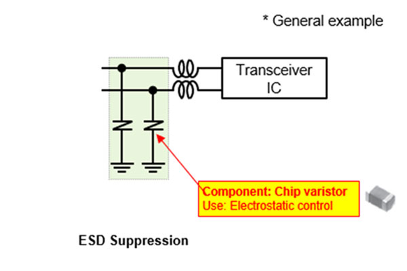
This circuit enables connectivity with external devices through communication protocols such as CAN or Ethernet. To safeguard sensitive components from electrical disturbances like noise or electrostatic discharge (ESD), protective elements are integrated into the design.
Key Component:
Chip Varistor: Chip varistors are employed to suppress ESD and transient noise without compromising communication signal integrity. Their compact size and fast response make them ideal for maintaining reliable data transmission in harsh environments.
Conclusion
Efficient cooling systems are essential for maintaining optimal operating temperatures and preventing equipment from overheating. As the global vehicle fleet—spanning both electric and internal combustion models—continues to expand, the demand for advanced cooling solutions and high-performance pumps will intensify. Increasing power outputs from automotive components further underscore the need for robust thermal management.
To meet these evolving requirements, electronic components integrated into cooling systems must deliver high current capacity, minimal energy loss, superior heat resistance, and precise temperature regulation. Panasonic Industry offers a comprehensive portfolio of components engineered to support the performance and reliability of modern automotive cooling systems.
Q.: How does the impeller, motor, and inverter work together within a cooling system pump to prevent overheating?
A.: The impeller moves water through the cooling system by spinning inside the pump housing. The motor provides the mechanical force to rotate the impeller. The inverter controls the motor speed by adjusting the electrical input, allowing the pump to regulate water flow based on the system’s cooling needs. This coordinated operation ensures continuous water circulation, preventing overheating of equipment.
Q.: What are the main electronic components in a cooling system pump's circuit architecture, and how do they contribute to reliable thermal management?
A.: Key electronic components include the noise filter (which suppresses electrical interference), voltage conversion circuits (which adjust voltage levels using switching elements like FETs), current measurement units (for monitoring motor output), gate drive circuits (which control switching elements), control circuits (which manage pump operation and react to temperature changes), DC/DC converters (supplying stable power), and communication interfaces (enabling data exchange). Together, these components ensure stable pump function, precise temperature regulation, and protection against electrical noise.
Q.: Why is the demand for advanced cooling system pumps increasing in both electric and internal combustion engine vehicles, and what performance features are essential to meet this demand?
A.: The rise in vehicle production, especially for electric vehicles, is increasing heat generation from powerful batteries and inverters, requiring more efficient cooling solutions. Essential pump features include high current capacity, minimal energy loss, excellent heat resistance, and precise temperature control to handle higher thermal loads and ensure system reliability.