Basic knowledge about capacitors
Basic structure of capacitors
To put it simply, a capacitors is a component which can store energy and release stored energy when necessary. Due to the fact that the energy stored (charge) is less than a battery, a capacitor can only provide current for a short time when releasing energy (discharge), but it can repeat charging and discharging cycles.
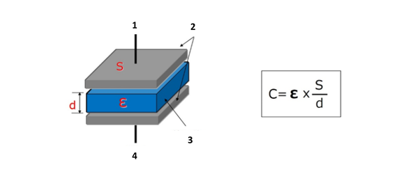
Capacitance (C) can become bigger, when permittivity of dielectric (Ɛ) is bigger, or surface of electrode (S) is bigger, or insulator (d) is thinner.
Structure:
- Terminal
- Electrode
- Insulator (dielectric)
- Terminal
Circuit symbol for capacitors
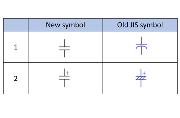
Circuit symbol which is used in a schematic is indicated in international standard IEC 60617. In Japan JIS C 0617 has been established (1997, 1999) adapting the international standard. There are partially changes made for circuit symbols for capacitors.
New symbols has been unified for education purpose, however, as actuality of company’s design site, there are still some old symbols continuously being utilized. Typical symbols for capacitors are shown here.
- Capacitors (no polarity)
- Electrolytic capacitors (with polarity)
Voltage and current of capacitors
Due to internal insulation, there is no direct current flow in a capacitor. Charging and discharging are carried out according to the change of applied voltage, so it seems as if current is flowing in a capacitor.
Current volume in a capacitor will become bigger if temporal change of voltage gets bigger, shown as following formula:
Ic = C * dVc/dt
- Ic: Capacitor Current [A]
- C: Capacitance [F]
- dVc/dt: Slope of V-t curve
Example 1: Waveform of charging and Discharging
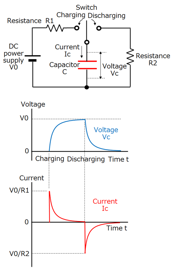
Let’s have a look at the voltage and current of a capacitor, which is being discharged after charging with DC power supply via resistors.
In a schematic, if we switch on charging side, there will be peak current of V0/R1 flowing through, and capacitor current will become lower while voltage Vc becomes higher.
Charging will complete when Vc = Vo and current will become zero.
Then if we switch on discharging side there will be peak current of V0/R2 flowing through, and capacitor current will become lower while voltage Vc becomes lower. Discharging will complete when Vc = 0 and current will become zero.
What we need to understand here is, that the volume of capacitor current is depending on the amount of capacitor voltage change.
Also, current of V0/R is flowing when switch is on, and when R = 0, theoretically there will be unlimited current flowing and charging discharging will complete in an instant. But in reality, influenced by the internal resistance (ESR) of capacitor, wiring resistance and reactance, there will be no unlimited current.
However, capacitor has much less resistance compared with battery, so it may possibly realize instantaneous charging and discharging.
Example 2: Waveform of AC
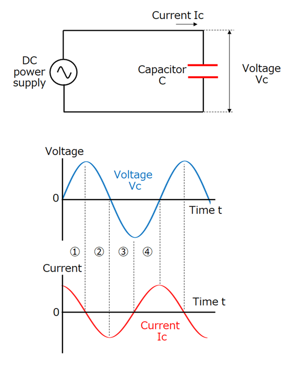
Let’s have a look at the voltage and current of a capacitor, which is applied with AC power supply.
In example 1, we mentioned that the magnitude of the current flowing through the capacitor follows the magnitude of the change in the voltage of the capacitor, and this is the same for AC waveforms.
- When the voltage rises from 0 V, the current flows greatly but as the voltage rising speed slows down the current decreases and when the voltage becomes maximum (zero voltage change) the current becomes zero.
- When the voltage begins to fall from the maximum value, a negative current begins to flow, and at the point where the voltage becomes zero (the change in voltage is the maximum), the current becomes maximum.
- and 4. area work in the same way as above.
Looking at the waveform of voltage and current, if the voltage waveform is a sinusoidal wave, the current waveform is also a sinusoidal wave, and the current waveform is shifted by 1/4 cycle before the voltage waveform (the phase of the current is 90 degrees ahead).
In addition, it can be seen that large current flows when the voltage change is large, in other words, the larger the high frequency voltage change has, the larger the current flows.
The flowing current (effective value) at this time is indicated by the following equation:
Ic = 2πf * C * Vc
- Ic: Capacitor current (Arms)
- π: Pi (3.14)
- f: Frequency (Hz)
- C: Capacitance (F)
- Vc: Power supply voltage (Vrms)
Basic usage of capacitors
As mentioned before, a capacitor has the property that (1) charging and discharging can be performed instantaneously, (2) direct current is impermissible but alternating current is passed, (3) alternating current is easier to pass if the frequency is higher, and we are using a capacitor with these characteristics in an electric circuit.
Here is a typical circuit example of how to use it.
Discharge circuit
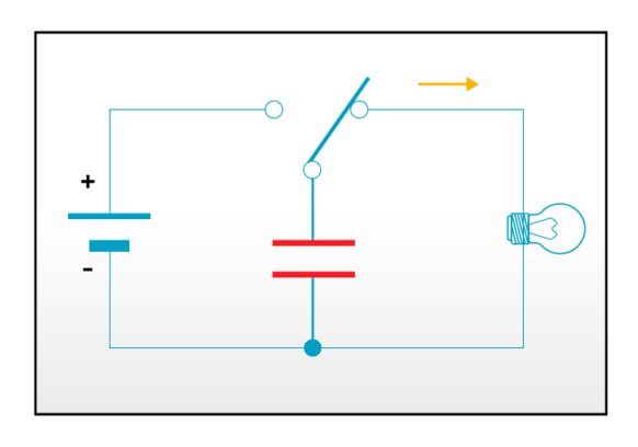
Discharge circuit is a circuit that operates the connected load by discharging the charge stored in the capacitor. Since a capacitor can instantaneously discharge large current, it is used as a camera strobe or backup power supply for emergency.
In the circuit example, when the switch is connected to the power supply side, the capacitor is charged and charging stops when charge accumulates to the power supply voltage.
When the switch is connected to the load (bulb) side, the capacitor starts discharging and the bulb lights up.
Smoothing circuit
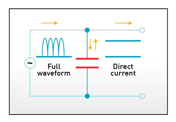
The smoothing circuit is a circuit that smooths pulsating flow after rectifying alternating current and converts it into direct current.
A typical example is a power supply circuit. The capacitor makes the voltage wave (ripple, pulsating flow) which is rectified by the diode bridge rectified (full-wave rectified in the circuit example) AC input voltage more flatter.
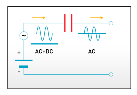
Decoupling circuit
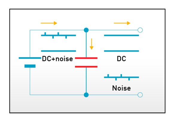
As its name implies, the decoupling circuit is a circuit that uses a capacitor to isolate signal coupling.
In this example, by placing a capacitor as shown in the figure, on the signal path including the AC component with high frequency (noise) in the basic AC, only the noise component with high frequency passes through the capacitor and becomes separated, and noises are not transmitted after this.
Coupling circuit
The coupling circuit is a circuit in which only AC component passes but no DC component passes.
It is used when you want to eliminate the influence of direct current component (also called DC cut etc.) in the amplifier circuit etc. of the audio signal.
Characteristics of capacitors
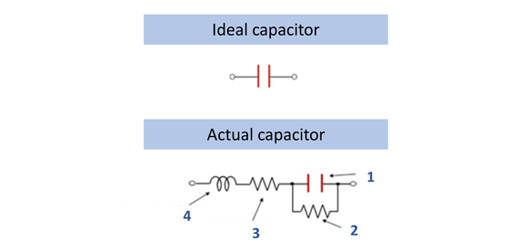
An ideal capacitor is only the capacitance component, but an actual capacitor contains resistance component and inductance component. These parasitic components have a great influence on the performance of the capacitor. The simplified equivalent circuit of a capacitor is shown in this figure.
- Capacitance (C)
- Insulation resistance (IR)
- Equivalent series resistance (ESR) or loss tangent (tanδ)
- Equivalent series inductance (ESL)
These components are summarized as below.
| Characteristic | Description |
| Capacitance (C) |
|
|
Equivalent series resistance (ESR) loss tangent (tanδ) |
|
| Insulation resistance (IR) |
|
| Equivalent series inductance (ESL) |
|
Impedance, in addition, is another important characteristic. Simply put, impedance is the ratio of the voltage and the current in the AC circuit, which corresponds to the resistance in the DC circuit. its symbol is Z and its unit is Ω as same as resistance.
The impedance (Z) of the capacitor is indicated by the following formula (1), and the absolute value of the impedance can be calculated by the following formula (2).
(1) Z = R + j 2 π f L + 1 / (j 2 π f C)
(2) Ι Z Ι = root (R2 + (2 π f L - 1 / (2 π f C))2
- Z: Impedance (Ω)
- R: Resistance = ESR (Ω)
- i: Imaginary number
- π: Pi (3.14)
- f: Frequency (Hz)
- I: Inductance = ESL (H)
- C: Capacitance (F)
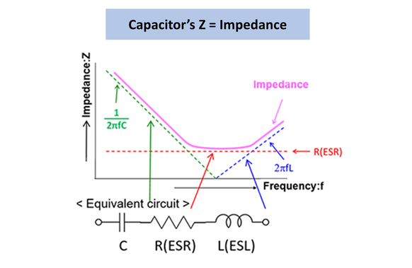
From the formulas above, we can see the following.
In the low frequency area, the impedance is almost determined by capacitance (C).
The impedance is determined by ESR at the self-resonant frequency (frequency coming from 2πf L = 1 / (2πf C)).
In the high frequency area, the impedance is almost determined by ESL.
This is shown in the graph on the right side.
The impedance Z of the capacitor decreases with the capacitance (C) up to the self-resonant frequency, but at self-resonant frequency the influence of C and ESL becomes zero and becomes ESR only, after that it becomes inductive (ESL) in high frequency area.
When using a capacitor in its main application of noise absorption (decoupling), the noise absorption effect is determined by impedance, therefore it is necessary to select parts according to the following points.
The noise frequency and the self-resonant frequency of the capacitor are close.
The ESR is small.
In case of high frequency noise, ESL is small.
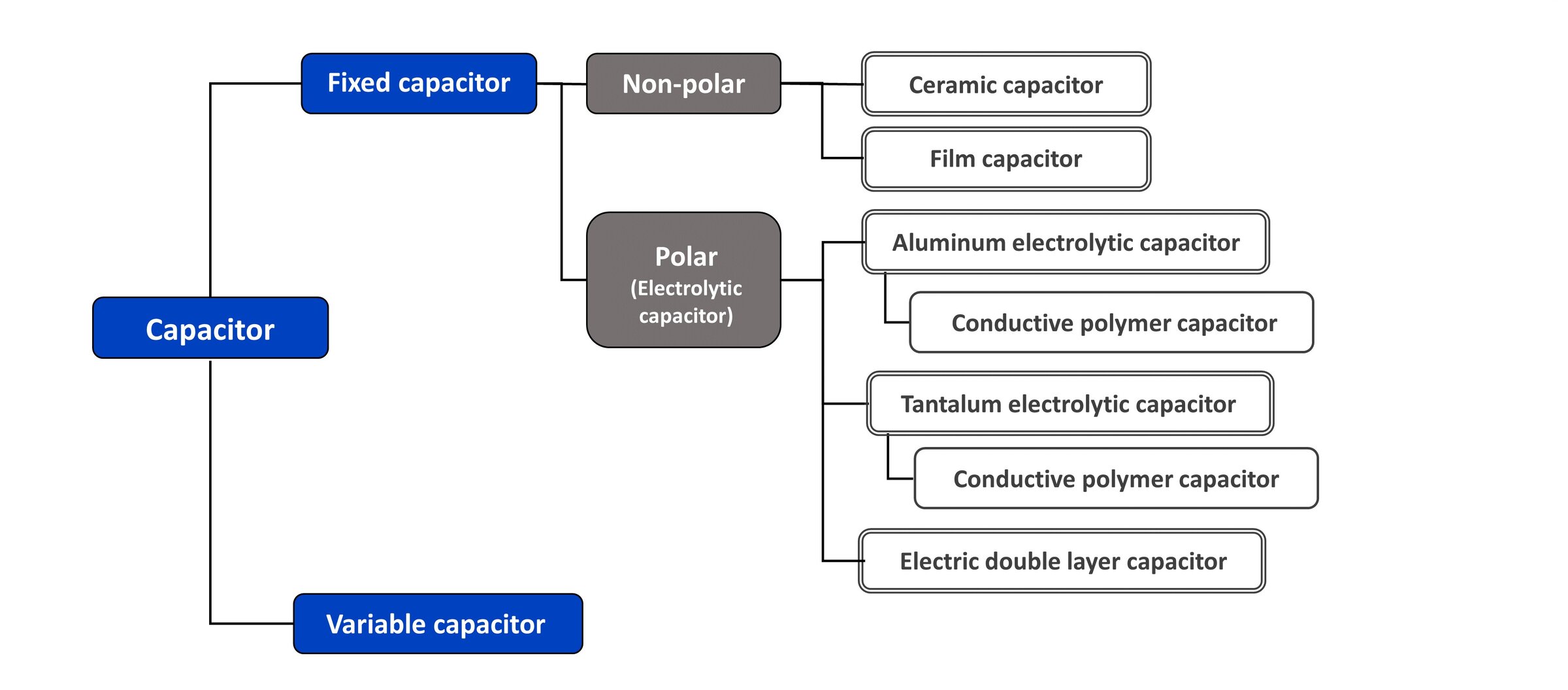
Types of capacitors
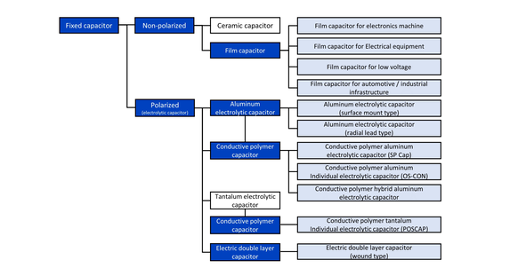
There are various types of capacitors depending on materials used and structure. Also, depending on the type, the characteristics are different, and it is selected in design based on these characteristics. Main types of capacitors are shown in the figure below.
Variable capacitor
Though fixed capacitors are mainstream for the capacitors, there are also variable capacitors that can change the capacitance in a certain range.
Generally, variable capacitors change the capacitance by changing the area of the counter electrode. Among variable capacitors, there are those that are frequently changed (tunable capacitors) in tuning radio stations, as well as those that are changed once only for adjustment (trimmer capacitors) when assembling the circuit.
Capacitance’s change is done with a knob or a screwdriver, but since it is a mechanically changing structure, it is difficult to make a capacitor with large capacitance and therefore it has a capacitance of small pF (picofarad) level.
Non-polarized capacitors and Polarized capacitors
Fixed capacitors are roughly divided into non-polarized capacitors and polarized capacitors.
A non-polarized capacitor is a capacitor whose polarity of the voltage applied to the capacitor terminals is not regulated, which means any terminal can be positive. If it is a non-polarized capacitor, it is possible to apply a voltage that goes up and down from the zero potential, so it can be used directly in an alternating current circuit.
Ceramic capacitors and film capacitors are mainstream for non-polarized capacitors, there are others such as mica capacitors, paper capacitors and air capacitors.
On the other hand, a polarized capacitor is a capacitor whose one of the two terminals is already set to be the plus side. If this is mistakenly used, the capacitor will fail. Therefore, there is a constraint that a polarized capacitor must be used with a DC voltage or a voltage fluctuating only on the plus side. However, a polarized capacitor is more widely used because it has the merit of being easier to obtain a capacitor with a small size and a large capacitance. Aluminum electrolytic capacitors, tantalum electrolytic capacitors, conductive polymer (electrolytic) capacitors, and electric double layer capacitors correspond to this category.
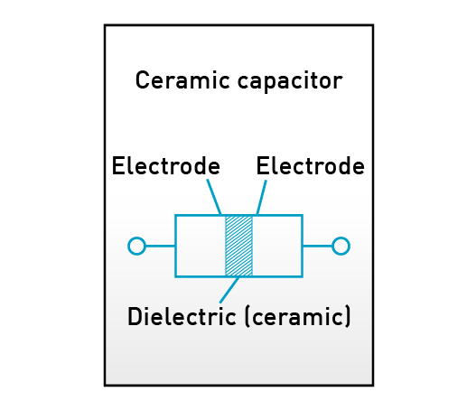
Ceramic capacitors
Ceramic capacitors are capacitors that use ceramics with a high dielectric constant for the dielectric and have the following features:
- Nonpolar
- Excellent high-frequency characteristics (low ESR)
- High heat resistance
- Long lifetime
Originally it was a high-voltage / low-capacitance single-plate capacitor. However, its use range has expanded greatly, after the appearance of multilayer ceramic capacitors which have small size and large capacitance due to the thin-film layered structure, as well as the appearance of temperature compensation which overcomes its temperature characteristic (big change ratio of capacitance due to temperature), and it became the most widely used capacitor among capacitor world. For temperature compensation, the shape is larger than the conventional high dielectric constant type and it is difficult to increase the capacitance, so it is used depending on the application.
However, ceramic capacitors have also disadvantage of DC bias characteristics (big change ratio of capacitance due to applied voltage), Piezoelectric effect (unusual noise due to vibration at high frequency), and cracking due to temperature /mechanical shock. Those points shall be checked when using it.
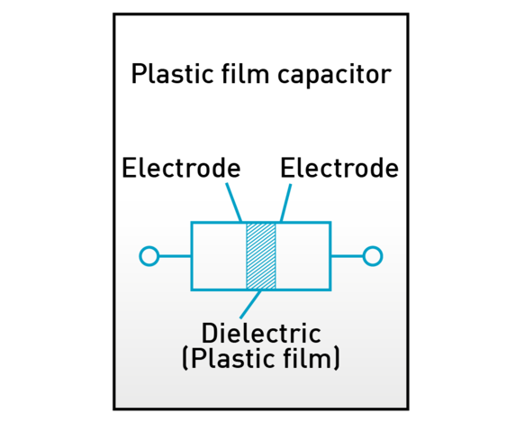
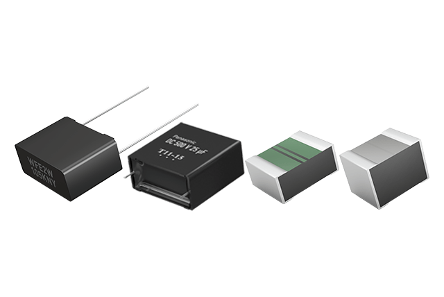
Film capacitors
Film capacitors are capacitors using plastic film for dielectric and have the following features:
- Nonpolar
- Excellent high-frequency characteristics (low ESR)
- Excellent temperature characteristics (Change rate of capacitance by temperature is small)
- Long lifetime
Compared to ceramic capacitors, film capacitors have low heat resistance; but they have excellent temperature characteristics and possible high precision of capacitance, and additionally no DC bias characteristics, squeal noise, or problem of cracking due to temperature / mechanical shocks. Therefore, they are capacitors with higher performance compared with ceramic capacitors, however, they have disadvantages such as large size and high price. Therefore, they have been used in voltage / capacitance range that cannot be covered by ceramic capacitors, with high performance and high precision.
Depending on the dielectric used, film capacitors have the following features, separately used in different applications.
| Item | PET Polyethylene terephthalate |
PP Polypropylene |
PPS Polyphenylene |
PEN Polyethylene naphthalate |
| Film unit price | ◎ | 〇 | × | △ |
| Miniaturization | ◎ | △ | 〇 | ◎ |
| Heat resistance | 〇 | △ | ◎ | ◎ |
| Humidity resistance | △ | ◎ | 〇 | △ |
| tanδ (ESR) | 〇 | ◎ | ◎ | 〇 |
| Usage |
|
|
|
|
◎: very good 〇: good △: not so good ×: bad
PET and PP are both dielectric for lead wire types. PET used to be used for general purpose due to its small size and low cost and PP used to be used for high frequency /current due to its excellent high frequency characteristics (low ESR). However, PP is also characterized by high safety and high humidity resistance, and also thanks to the development of miniaturization technology of PP film capacitors, PP is currently more widely used.
PPS and PEN are used for surface mount film capacitors because of their high temperature resistance. Those electrical characteristics indicate that PEN is close to PET and PPS is close to PP.
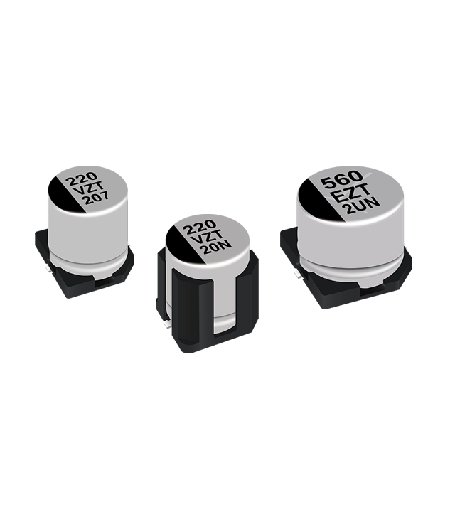
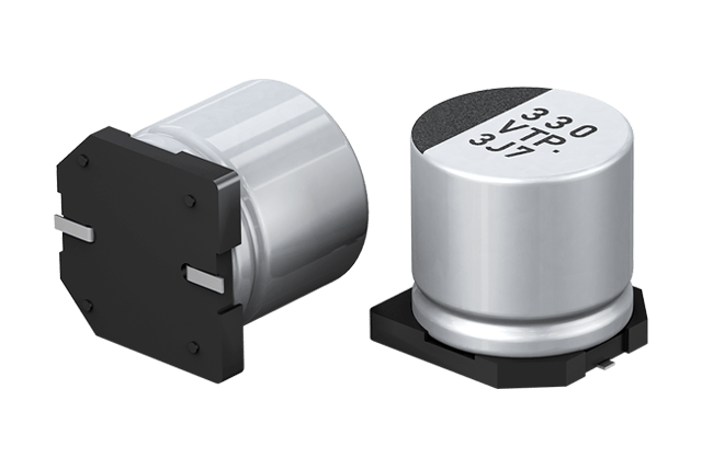
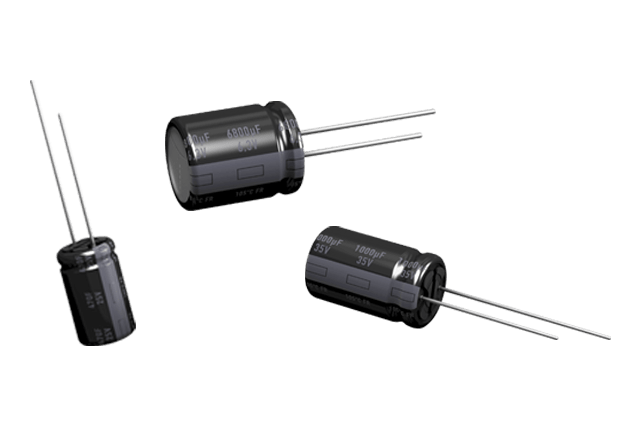
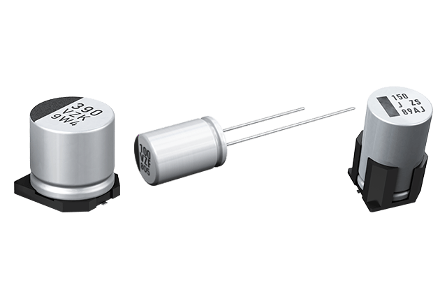
Aluminum electrolytic capacitors
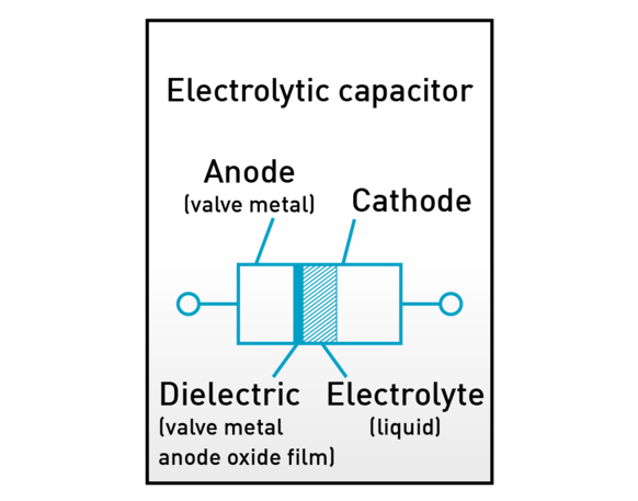
Aluminum electrolytic capacitors have a structure in which an aluminum oxide film, which becomes a dielectric, is formed on the surface of the aluminum foil of the anode, and electrolyte liquid (consisting of a solvent in which electrolyte is dissolved) is used as an electrolyte (cathode).
One feature of aluminum electrolytic capacitors is their large capacity, which is achieved by increasing the electrode surface area (S) through the etching of the aluminum foil surface to form irregularities and by forming ultra-thin (d) of oxide films at the Angstrom level.
However, their equivalent series resistance (ESR) is higher than that of ceramic and film capacitors.
Aluminum electrolytic capacitors are products with a limited life. The electrolyte liquid vaporizes depending on the temperature and gradually penetrates the sealing rubber. Consequently, the capacity decreases and ESR rises over time, eventually leading it to be in an open state (electrolyte liquid having dried up).
When estimating the life of aluminum electrolytic capacitors, the "10ºC 2-fold law" can usually be applied.
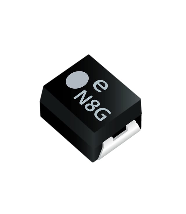
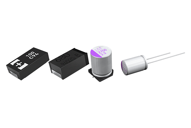
Tantalum electrolytic capacitors
The basic structure of tantalum electrolytic capacitors is almost the same as that of aluminum electrolytic capacitors. Tantalum pentoxide to be a dielectric is formed on the surface of the sintered body of the tantalum metal powder which is to be the anode, and manganese dioxide (solid) is used as electrolyte.
Tantalum electrolytic capacitors are smaller than aluminum electrolytic capacitors, excellent in frequency characteristics, and have a long lifetime (electrolyte is solid).
However, since the failure mode is short-circuited and there is a danger of ignition, safety countermeasures are necessary.
Conductive polymer capacitors
Conductive polymer capacitors are capacitors in which the electrolyte is conductive polymer (solid).
The electrical conductivity of the conductive polymer is as high as 10,000 times of electrolytic solution of aluminum electrolytic capacitors and 1,000 times of manganese dioxide of tantalum electrolytic capacitors, and its equivalent series resistance (ESR) is low, so it’s more advantageous than other electrolytic capacitors for ripple absorption application.
Electric double layer capacitors
A electric double layer capacitor is a special capacitor having an intermediate capacitance between an aluminum electrolytic capacitor and a secondary battery (battery), and its capacitance density is about 1,000 times or more of an aluminum electrolytic capacitor, about 1/10 of a secondary battery.
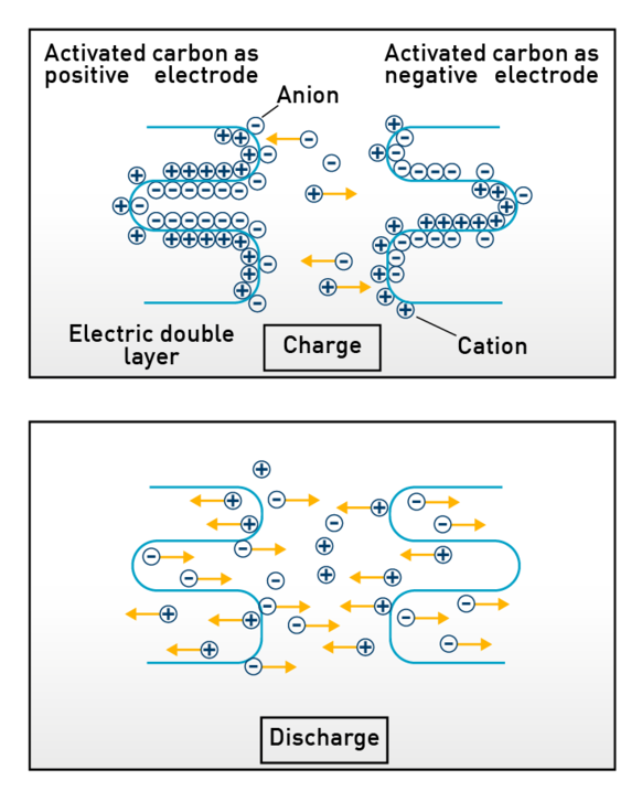
There is no dielectric like an electrolytic capacitor in an electric double layer capacitor. Instead, it uses the electric double layer that is formed at the interface between the electrode and the electrolyte as function of the dielectric. This is where the name “electric double layer capacitor” comes from.
Charge and discharge of electric double layer capacitors is based on the adsorption / desorption of ions on the electrode surface of activated carbon which is used for positive and negative electrodes. Changes of the double layer due to this charging / discharging are shown in following figure.
An electric double layer capacitor has the following features compared with a secondary battery.
- The number of charge / discharge cycles hardly affects the characteristic deterioration (maintenance free)
- Easy charging / discharging (dischargeable up to 0 V, energy level can be known with terminal voltage, has the following features, chargeable with both small and large current)
- Not subject to environmental regulations (collection, disposal, tariffs) like batteries
Therefore, it is used as a backup power supply, such as data protection of IC memory during power off.
Summary of types and features of capacitors
So far we have explained characteristics of various capacitors, and let’s summarize the comparison of each capacitors in the table below.
| Item | *Ceramic | Film | Aluminum electrolytic |
Tantalum electrolytic |
Conductive polymer |
Electric double layer |
| High capacitance | △ | × | 〇 | 〇 | △ | ◎ |
| High voltage | 〇 | ◎ | 〇 | △ | △ | × |
| Long lifetime | ◎ | ◎ | △ | 〇 | 〇 | △ |
| Temp. characteristics | △ | ◎ | △ | 〇 | ◎ | △ |
| Low ESR | ◎ | ◎ | × | △ | 〇 | × |
| Polarity | no | no | yes | yes | yes | yes |
| Others | Big capacitance change by DC bias |
|
|
Easy ignition in case of failure | ||
| Main application |
|
|
|
|
|
|
◎: very good 〇: good △: not so good ×: bad
* It shows characteristics of MLCC
Panasonic product line-up overview