Technological Innovations in the Transportation Sector Enabled by Panasonic Passive Components
Passive Components at the Heart of Modern Mobility Innovations
Panasonic’s passive components are a cornerstone of today’s advanced mobility solutions. They play an important role in enabling electric vehicles, high‑speed rail systems, electric bicycles, and the dependable operation of agricultural machinery.
Technological progress is closely tied to the advancement of transportation, making innovative transport systems a key driver of modern development. Today’s mobility landscape spans a broad range of applications—from passenger cars and commercial vehicles to railway systems, electric bicycles, and Automated Guided Vehicles (AGVs) used in industrial and agricultural environments. At the heart of all these technologies lies a fundamental element: electronics, and in particular, high‑quality passive components. Their continuous evolution is essential to ensuring the performance, safety, and reliability of modern transportation.
By leveraging Panasonic’s state‑of‑the‑art LCR technology—recognized for outstanding performance, efficiency, safety, and reliability—transportation networks are becoming safer, more intelligent, and more efficient than ever before.
Changing Market Requirements in the Transportation Sector
The acceleration of electrification and automation has radically changed the requirements for components across the transportation industry. They must be highly reliable and handle high currents.
Consider also the rapid growth of the electric bicycle market:
- Increased motor power: from 500W to over 750W
- Increase in system voltage from 36V to 48V, and even 60V
- Integrated design: compact modules with high functionality
To meet these changing requirements, key features of components include:
- High current performance (low DCR and ESR for increased efficiency)
- Thermal stability (guaranteed operation over a wide temperature range, e.g., from -55°C to 170°C)
- Miniaturization (space-saving components for surface mount, SMD)
- Reduction of electromagnetic interference (reduced level of emitted noise)
- Long life and high performance throughout the service life
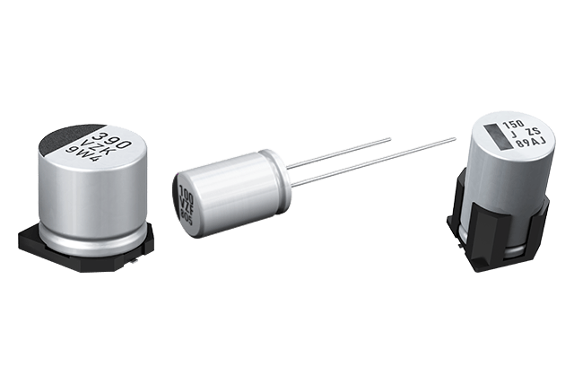
Hybrid Capacitors – Performance and Durability
Leading Panasonic hybrid capacitors with ultra-low ESR and high capacitance enable the realization of compact designs without sacrificing performance, facilitating the creation of integrated infotainment and control systems in vehicles.
From ensuring smooth, reliable operation in electric and autonomous vehicles, through supporting the high-speed requirements of railway systems, to powering electric bicycle drives and agricultural machinery — Panasonic passive components form the basis of modern mobile solutions.
Technical Challenges in Transportation Applications
High‑current handling
Electric bicycles and AGVs with power outputs ranging from 500 W to 6 kW require DC‑link capacitors capable of handling ripple currents between 20A and 60A. Traditional electrolytic capacitors often need to be connected in parallel to meet these requirements, resulting in increased component count and larger printed circuit board (PCB) footprints.
Long‑term reliability
Modern electric vehicles and AGVs are increasingly expected to operate reliably for up to 10 years, with more than 4,000 operating hours at temperatures as high as 125 °C. These demands exceed the typical 2,000‑hour lifetime ratings of conventional electrolytic capacitors, presenting a significant reliability challenge.
Safety under fault conditions
While polymer capacitors offer excellent high‑current performance, their failure mode can involve short‑circuiting, which may cause fire hazards or unexpected system shutdowns. Automotive and industrial standards therefore require capacitors with open‑circuit failure behavior in emergency conditions to prevent secondary damage and ensure system safety.
Panasonic Hybrid Capacitor Technology
Our hybrid capacitors combine electrolytic and polymer technologies to comprehensively address the issues described above.
Performance comparison (e.g., 47µF, 35V):
- Combining high reliability of electrolytic capacitors (low LC, open mode) with high current performance of polymer capacitors (low ESR);
- Twice the durability compared to conventional capacitors
- 4.5-fold increase in allowable ripple current
Hybrid capacitor has high reliability (Low LC, Open mode) and is suitable for large current (Low ESR).
legend:◯ : good ✕ : bad
| 35V47uF (Dia 6.3mm) | E-Cap | Hybrid | Polymer Cap |
| Electrolyte | Liquid | Polymer + Liquid | Polymer |
| LC (mA) | ◯ 0.01CV | ◯ 0.01CV | ✕ 0.2CV |
| Life end mode | ◯ Open | ◯ Open | ✕ Open (Accidental short) |
| Humidity | ◯ 85℃ 85%RH | ◯ 85℃ 85%RH | ✕ 60℃ 95%RH |
| Endurance | ✕ 125℃ 2000h | ◯ 125℃ 4000h | ✕ 125℃ 2000h |
| Ripple current (125℃ 100kHz) | ✕ 197 mA | ◯ 900 mA | ◯ 1000 mA (* 3100mA at 105℃) |
| ESR (20℃ 100kHz) | ✕ 450 mΩ | ◯ 60 mΩ | ◯ 26 mΩ |
| Low temperature, High-frequency characteristics | ✕ Unstable | ◯ Stable | ◯ Stable |
Example Application in Electric Bicycles
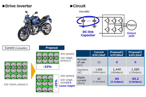
Below are two proposals for using Panasonic hybrid capacitors in electric bicycle circuits. The initial assumption is a 6kW drive inverter design for a three-phase motor. The circuit is powered by a 48V lithium-ion battery.
Conventional design would involve using 12 capacitors of 150µF (63V) with dimensions φ10×16.5mm.
Proposal 1 (ZUU): 63V, 180µF, φ10×16.5mm × 8 pcs.
- Total capacity: 1440 µF
- Ripple current: 44A RMS
- Number of components reduced by 33%
Proposal 2 (ZUU Low-Profile): 63V, 120µF, φ10×12.5mm × 9 pcs
- Low-profile design (height reduced from 16.5mm to 12.5mm, a reduction of 24%).
Increased circuit performance using the proposed components
Key Product Series
The most important Panasonic product series within the hybrid components portfolio:
ZTU – increased capacity or miniaturization,
ZUU – very high capacity and handling significant ripple current.
In the table below, the distinguishing features of each series are presented:
| Series | Capacity | Ripple Current | Miniaturization |
| ZTU | 1.7 times greater than the basic hybrid series (e.g., 330µF → 560µF, φ10×10.2mm) | 1.8 times (e.g., 2900mA → 3500mA) | φ10×10.2mm → φ8×10.2mm (smaller casing with the same capacity) |
| ZUU | Series with the highest capacity up to 1000µF | Largest series ripple current up to 6100mA | Cost and space savings thanks to 1-to-many replacements |
Example: Application in Automotive
One of the key areas where Panasonic components contribute to reduced circuit size is automotive electronics. The following example illustrates how such miniaturization can be achieved in a real-world application.
EXAMPLE: ELECTRIC POWER STEERING (12V, 500W)
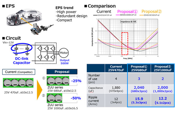
In a conventional design, four capacitors rated at 25 V with a capacitance of 470 µF are required. Each capacitor has dimensions of Ø10 × 12.5mm.
By using Panasonic components from the ZUU series, the design can be simplified to just two capacitors rated at 25 V and 1000µF, each measuring Ø10 × 16.5mm.
This optimized configuration results in the following performance parameters:
- Total capacitance: 2000 µF (+6.4%)
- Allowable ripple current: 12.2 A RMS
- Number of components reduced by 50%.
Comparison of both circuits considering the required PCB area
EXAMPLE: COOLING FAN (24V, 4KW, THREE-PHASE MOTOR)
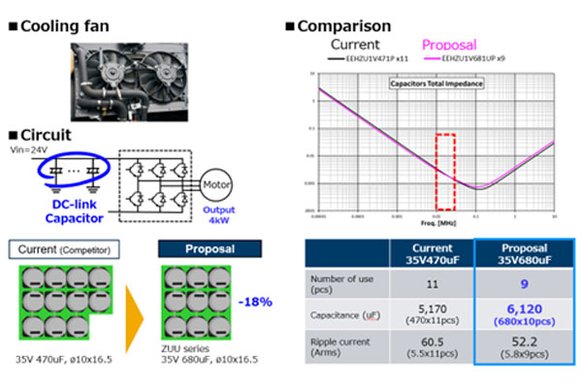
In a standard design, 11 capacitors of 470µF/35V would be used, each measuring φ10×16.5mm. ZUU components reduce this number to 9 pcs. of 680µF/35V components (φ10×16.5mm).
This means a change:
- 18% increase in total capacity (6120 µF)
- 18% decrease in number of components.
Hybrid capacitors not only improve parameters but also reduce PCB area
EXAMPLE: DC‑DC OBC ONBOARD CHARGER CONVERTER
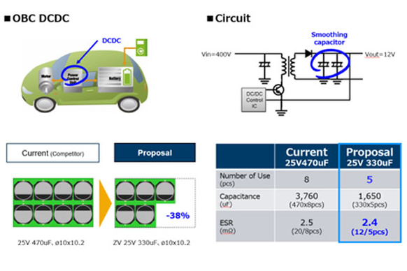
A DC‑DC onboard charger (OBC) converter of this type typically operates with a 400V input and a 12V output. In a conventional design, the circuit would require eight 470µF / 25V capacitors, each with dimensions of Ø10 × 10.2mm.
By using Panasonic ZV Series capacitors, the design can be optimized to just five components rated at 330 µF / 25V, while maintaining the same Ø10 × 10.2mm footprint.
This approach delivers two key benefits:
- 38% reduction in component count
- Equivalent electrical performance, enabled by the low ESR characteristics of the ZV series
Better ESR parameters allow the use of a capacitor arrangement with a smaller capacity
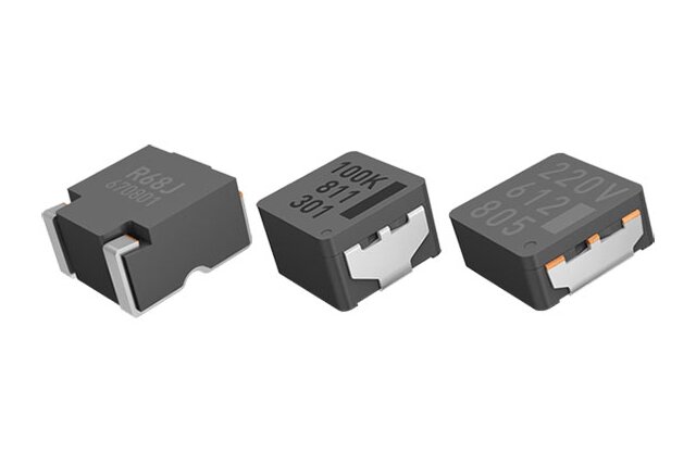
Compact Power Inductor Design
Our power inductors leverage advanced materials science and cutting-edge engineering to deliver outstanding performance across a broad range of applications. Utilizing Panasonic’s patented metal composite (MC) core technology, these power inductors support current ratings of up to 103A while maintaining compact footprints ranging from 5 × 5mm to 15 × 15mm.
The innovative MC core structure enables low DC resistance, high saturation current, and excellent heat dissipation, ensuring stable and efficient power conversion even in space‑constrained designs. Designed for demanding environments such as automotive, industrial, and telecommunications systems, Panasonic power inductors offer designers a flexible, high‑performance solution for DC‑DC converters, voltage regulators, and next‑generation power modules.
Technical Challenges and Solutions
Managing Electromagnetic Interference (EMI)
High‑frequency switching in electric bicycles and AGVs generates significant electromagnetic interference. Conventional inductors with ferrite cores often exhibit high magnetic flux leakage, making compliance with electromagnetic compatibility (EMC) requirements difficult. Panasonic’s metal composite (MC) core technology significantly reduces flux leakage, helping designers meet stringent EMC standards more easily.
Overcoming Miniaturization Limits
As system voltages increase to 48–60V, must h inductors handle currents exceeding 5A—often without increasing component size. Traditional solutions struggle to balance current capability with compact form factors. Panasonic MC core inductors enable high current handling while maintaining a small footprint, supporting space‑efficient, high‑power designs.
Effective Thermal Management
High current operation leads to temperature rise, which can impact inductance stability and overall circuit performance, particularly in applications located close to motors. Panasonic power inductors are designed for excellent thermal stability and industry‑leading reliability, ensuring consistent performance even under demanding operating conditions.
Our Solution
The electrical and thermal performance characteristics of Panasonic’s MC Core inductors directly address all of the challenges outlined above, offering a robust and efficient solution for high‑current, space‑constrained applications.
DIMENSIONS COMPARISON

See a comparison between compact Panasonic MC core inductor and standard ferrite‑based inductive components at 22 µH.
The table highlights a significant difference in size and saturation current value
LOW ELECTROMAGNETIC INTERFERENCE
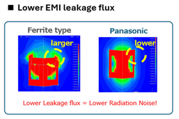
Power Inductors with a metal composite core exhibit significantly lower magnetic flux loss compared to conventional ferrite‑based components. The reduced stray flux results in lower radiated noise, making it easier to comply with EMC requirements in demanding applications such as automotive systems and AGVs.
Comparison of electromagnetic radiation for ferrite and MC elements from Panasonic
INDUCTANCE STABILITY
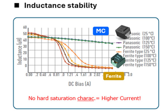
Inductance Stability
A key advantage of Panasonic’s MC power inductor is their exceptional inductance stability, characterized by three main attributes:
- No hard saturation behavior, ensuring predictable performance under load
- Stable inductance across the full operating temperature range
- High tolerance to transient current peaks, even in demanding conditions
Hard saturation characteristic for ferrite elements and MC core elements
RELIABILITY
It is also worth noting a few features of Panasonic power inductors (specific to selected models). They relate to the durability of these components. These include:
- Compliance with AEC-Q200 standard
- Operating temperature range from -40°C to 150°C
- Resistance to vibrations up to 50G
- Withstand voltage: 80V (provides a 67% margin for 48V systems).
APPLICATION IN ELECTRIC BICYCLE/AGV CIRCUITS
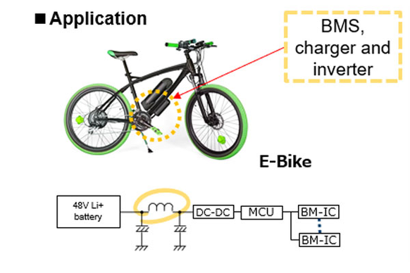
The illustrations show the application of Panasonic MC core power indutors in typical circuits for smaller electric vehicles.
In the diagram, the coil is placed to stabilize the current flowing from the battery pack
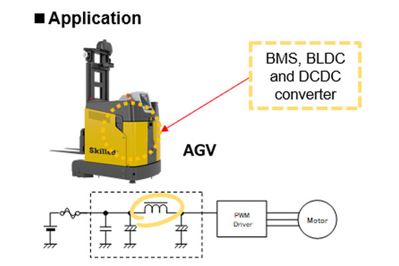
Filtering coil in the power supply circuit of a three-phase motor controller.
WORKING IN BATTERY SYSTEMS
It is worth noting a number of advantages associated with the use of Panasonic power inductors in lithium-ion battery systems (e.g., 48V).
- Space savings due to BMS board design: achieved through miniaturization (reducing area by 57%, reducing volume by 74%).
- Simplified measures to counteract electromagnetic interference: thanks to low stray flux
- Provided design margin: thanks to high saturation current capacity
- Increased reliability: maintained thanks to thermal stability
- Handling higher system voltages: suitable for applications from 48V–60V and higher
- High resistance to high voltage and current: optimized for next-generation power systems
- Thermal stability of inductive coils: ensures consistent performance at elevated temperatures
- Integrated compact designs: ideal for low-profile, surface-mounted (SMD) applications
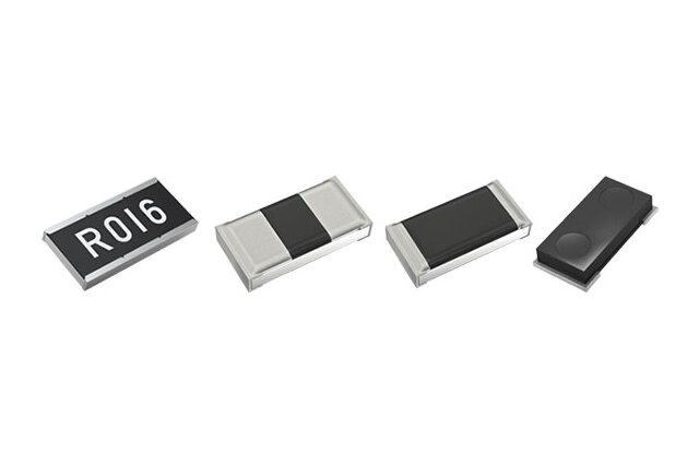
High‑Performance Chip Resistors
Panasonic chip resistors play a vital role in transportation applications where compact design, high power handling, accuracy, and resistance to harsh conditions are essential.
The ERJP and ERJB series combine high power capability with small form factors, making them well suited for demanding circuits in electric vehicles and e‑bikes. For applications requiring precise signal control, the ERA series delivers tight tolerances and low temperature coefficient of resistance (TCR). In challenging environments such as agricultural machinery and railway systems, the ERJU series offers sulfur resistance and proven long‑term reliability—helping ensure safe, efficient, and dependable operation across a wide range of transportation platforms.
Required Circuit Characteristics in the Transportation Sector
The table below presents typical resistor requirements for transportation applications and indicates which Panasonic products are best suited for each use case.
| Function | Key Requirements | Technical Challenges | Recommended Solutions |
| Voltage measurement | High precision (±0.1%), low temperature coefficient (TCR) (~25 ppm), long-term stability | Accurate detection of small voltage changes and temperature drift | High-precision ERA series resistors |
| Voltage divider | High voltage resistance (500V), wide resistance range (10MΩ), compliance with creepage and clearance requirements for high-voltage safety | Series connection of resistors for high voltage increases component count and PCB area and complicates creepage requirements on compact PCBs | High-voltage resistors: ERA8P and ERJPM8 series |
| Current sensing | Low resistance, high power (1…3W), temperature stability (155°C). | Heat generated by high current combined with vibration and high-temperature stress can lead to measurement errors | Current sensing resistors: ERJB/D and ERJ*BW series |
| Gate control | High power (3W), excellent heat dissipation during continuous operation, thermal stability in harsh automotive environments | Continuous power dissipation in gate control causes thermal stress and resistance drift, affecting reliability | High-power resistors ERJP or ERJB/D |
| Environmental reliability | Resistance to environmental conditions (sulfur, vibration), long-term reliability | Sulfur-containing gases, humidity, and exposure to high temperatures in harsh environments | Sulfur-resistant resistors: ERJU/S serie |
ADDRESSING SPECIFIC CHALLENGES
The features of the individual series described in the table above have a real and significant impact on electronic circuit design. Below, these aspects are presented using specific examples.
Voltage Measurement and the ERA Series
Accurately measuring small voltage variations requires minimizing resistance drift caused by temperature changes. Transportation systems are exposed to harsh operating conditions, with temperatures typically ranging from –40 °C up to 125 °C or beyond. As a result, low temperature coefficient of resistance (TCR) and strong long-term stability are critical to maintaining reliable performance. These requirements are effectively met by ERA series thin-film resistors.
Key features:
- Resistance tolerance of ±0.1%, TCR: ±25 ppm/K;
- Limited degradation of performance and reliability during long-term use and temperature fluctuations;
- Improved overall tolerance ensures long-term reliability.
High reliability is achieved through the use of a patented resistive material (±0.1% tolerance after endurance testing).
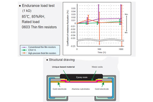
Construction of ERA thin-film resistors and their stable
characteristics over time:
Voltage Dividers with ERA8P and ERJPM8 Series
In BMS voltage‑sensing applications, series‑connected battery cells can produce high voltages ranging from 300V to 500V. To handle this, many low-voltage resistors are traditionally connected in series, increasing the number of components and required PCB area, creating design and cost challenges. In addition, ensuring sufficient creepage distance between high-voltage nodes on a compact PCB is crucial for safety compliance, further complicating the circuit design. ERA8P and ERJPM8 series resistors address these challenges by offering a more efficient and compact solution for high‑voltage divider networks.
Key characteristics include:
- Maximum element voltage rating of 500V
- Resistance tolerance: ±0.1%, TCR: ±15 ppm/K (ERA8P)
- Compliance with the AEC-Q200
- Minimized resistor count
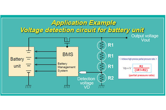
Use of Panasonic resistors to build a voltage divider
By achieving a highly accurate voltage division ratio (VD = V × R2/(3R1+R2)) in the battery voltage sensing circuit, BMS accuracy is significantly improved. In addition, Panasonic components allow a reduction in the number of resistors used:
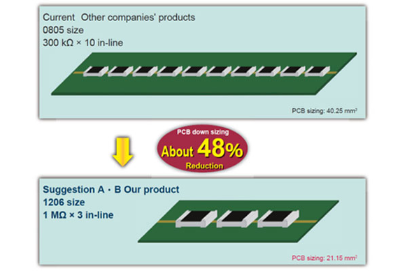
- Conventional design: 0805 size, 300kΩ × 10 pcs, PCB area: 40.25mm²
- Proposed design: 1206 size, 1MΩ × 3 pcs, PCB area: 21.15mm² (48% reduction).
It should be noted that the actual reduction in component count depends on insulation distance regulations.
Comparison of circuits built using typical resistors and ERJPM8 series
| Resistance value x usage | Resistance tolerance (%) | TCR (x10⁻⁶/K) | Working voltage (V) | PCB sizing* (mm²) | |
| Current: Other company 2012 Thin film resistance |
300 kΩ x 10 in-line |
± 0.1 | ± 25 | 150 x 10 p = 1500 |
40.25 |
| Suggestion A : ERA8PEB 1206 Thin film high resistance |
1 MΩ x 3 in-line |
± 0.1 | ± 25 | 500 x 3 p = 1500 |
21.15 (About 48% Reduction) |
| Suggestion B : ERJPM8F 1206 High resistance and high withstand voltage |
1 MΩ x 3 in-line |
± 1 | ± 100 | 500 x 3 p = 1500 |
21.15 (About 48% Reduction) |
CURRENT SENSING: ERJB/D AND ERJ*BW SERIES
High current levels can generate substantial heat, which—when combined with vibration and thermal stress—may lead to resistance drift and measurement inaccuracies. Current‑sensing circuits used in applications such as EV traction systems, charging infrastructure, and fuse protection therefore require low‑resistance, high‑power resistors with exceptional stability and reliability. To meet these demanding requirements, Panasonic offers the ERJB/D and ERJ*BW series of current‑sensing components.
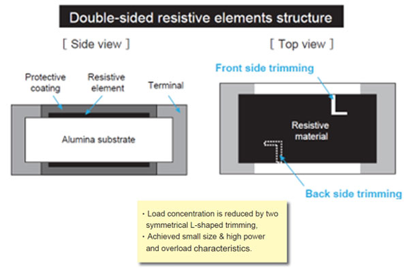
The ERJBW series (double-sided resistive element type) features very low resistance values (down to 5 mΩ) and a unique construction that provides high power in a smaller package**, contributing to PCB size reduction.
Cross-section showing the double-sided resistive element structure
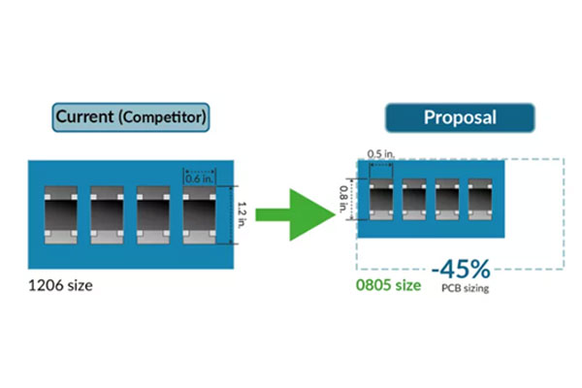
Size reduction resulting from the use of components in the 0805 package.
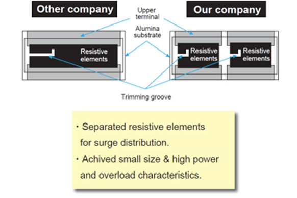
The ERJB/D series (wide terminal type) reduces the number of components, enabling miniaturization, weight reduction, and PCB cost savings. The multi-element resistive structure distributes the load, limiting surface temperature rise at the hottest points. The elongated terminal design mitigates thermal shock compared to standard terminal resistors.
Difference in construction between Panasonic resistors and components from other manufacturers
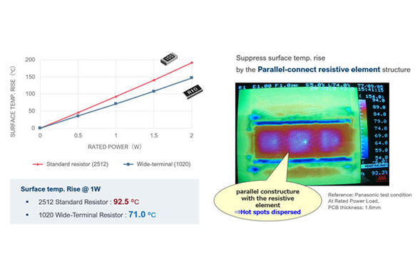
The structure with separated resistive elements distributes the load more effectively, resulting in improved thermal characteristics. Precise measurements illustrate this advantage using charts and thermal images.
Reduced heating of resistors made using multiple resistive elements
TRANSISTOR GATE DRIVE: ERJP AND ERJB SERIES
Gate drive circuits used in EV traction systems and power inverters are subject to continuous power dissipation during high‑speed switching, resulting in significant heat generation. Conventional resistors often lack the required power handling and thermal management capabilities, which can lead to resistance drift and reduced operational lifetime. Panasonic’s ERJPA/P0 and ERJB/D series resistors are high‑power solutions designed with optimized heat dissipation and a stable thermal structure to ensure precise and reliable gate drive control.
ERJPA/P0 AND ERJB/D RESISTORS
ERJB/D series resistors can replace standard chip resistors to support PCB miniaturization while reducing overall device weight. Their high surge resistance helps prevent component failure and provides an optimal safety margin during circuit design. Featuring a specialized internal structure, these high‑power components distribute electrical and thermal loads evenly, minimizing localized stress and enhancing long‑term reliability.
Resistive element structure in ERJPA series components.
ENVIRONMENTAL RESISTANCE: ERJU/ERJS SERIES
In outdoor or sulfur‑rich environments—such as industrial AGVs and agricultural machinery—resistors with silver‑based terminations are vulnerable to sulfidation, which can result in open circuits or degraded electrical performance. When combined with high humidity and elevated temperatures, these conditions significantly increase the risk of long‑term failure. The materials and construction used in Panasonic’s ERJU and ERJS series resistors are specifically designed to minimize sulfidation effects and enhance reliability in harsh operating environments.
Sulfur-resistance properties:
- Prevents open circuits caused by sulfidation, increasing reliability;
- Eliminates the need for PCB sealing, reducing costs;
- Compliance with the AEC-Q200
- Operating temperature range –55°C to 155°C.
Diverse ERJU series offerings include:
- High-precision components – ERJU*R series (0402 to 0805, 0.5% tolerance);
- Compact high-power resistors – ERJUP series (0603 to 1206, 0.5W in 0805);
- Low-resistance versions – ERJU*S/Q series (0805, 0.1Ω to 1Ω, 10 mΩ to 1Ω);
- High-power type (wide terminals) – ERJC series (1020 size, 2W, 10 mΩ to 1Ω).
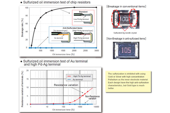
The photos and chart illustrate contact degradation caused by sulfidation and the resistance to harmful factors demonstrated by Panasonic components:
SUMMARY
Panasonic continuously strengthens its portfolio with innovative components tailored for the transportation sector. By delivering solutions that support vehicle electrification and automation, the company helps make mobility safer, more efficient, seamlessly integrated, and more cost‑effective to manufacture.
The appendix below summarizes the products described and their potential applications.
E-bike, AGV Drive (48...60 V, 500...6000 W)
- DC-link capacitors: ZUU / ZVU / ZSU (high ripple current, long lifetime, low profile).
- Shunt resistors: ERJD (±100 ppm/K, comparable to metal shunts)
- Inductors: ETQP4M220KV (MC core, low EMI, compact)
- High-precision resistors: ERAV/K/P (high accuracy)
Automotive BMS (12...48 V)
- DC-link capacitors: ZUU / ZSU (125°C, 4000h)
- High-voltage resistors: ERA8P / ERJPM8 (500V element voltage limit, ±0.1%)
- High-precision resistors: ERAA, ERAV/K (0.05%, ±10…25 ppm/K)
Electric Vehicle Electronics (EPS, OBC, Inverter)
- DC-link capacitors: ZUU / ZV (maximum ripple current)
- Current sensing resistors: ERJD, ERJBW (high-power current measurement)
- High-voltage resistors: ERA8P / ERJPM8 (500 V, ±0.1%)
AGV Control and Monitoring (Harsh Outdoor Conditions)
- Power circuits: ERJU / ERJS (sulfur-resistant resistors) + ZUU / ZSU
- Control circuits: ERJUR (high-precision sulfur-resistant resistors)
- Current sensing: ERJUS/Q (low resistance, sulfur-resistant)
See source from TME